Add workiece dimensions automatically
With the new version SMARTElectrode 12.0.2.0, workpiece dimensions can now be created automatically.
Use of the my_drawing_format.cfg
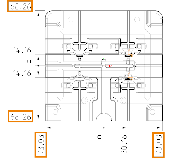
The use of the configuration file is briefly explained here using an example. On the position sheet of the electrodes the workpiece dimensions should be created as ordinate dimensions. The desired result looks as follows:
The following information is required for the configuration file:
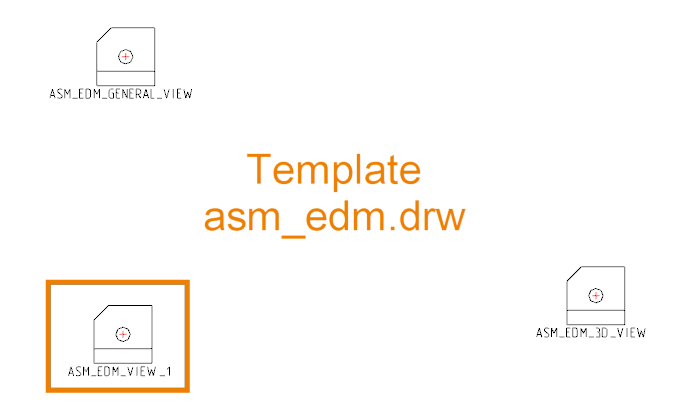
- Name of the drawing template
- Name of the drawing view
- 1st reference
- 2nd reference if necessary
- Orientation 1: vertical / 2: horizontal / 3: direct
- Distance from the edge of the view. < 0 means offset to the left/down. > 0 means offset to the right/up.
- Conversion to ordinate dimensioning YES/NO.
Drawing template and drawing view can be found in the templates in the configuration.
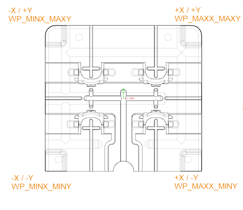
SMARTElectrode calculates the corner points of the workpiece outline for each drawing view. These are available as named references.
Orientation, offset and conversion to ordinate are set according to the desired result. The complete entries for generating the dimensions look as follows:
ASM_EDM    ASM_EDM_VIEW_1    OP_ASM_REF_CSYS WP_MINX_MINY    2    -15    YES
ASM_EDM    ASM_EDM_VIEW_1    OP_ASM_REF_CSYS WP_MAXX_MINY    2    -15    YES
ASM_EDM    ASM_EDM_VIEW_1    OP_ASM_REF_CSYS WP_MINX_MINY    1    -15    YES
ASM_EDM    ASM_EDM_VIEW_1    OP_ASM_REF_CSYS WP_MINX_MAXY    1    -15    YES
Here “OP_ASM_REF_CSYS” is the zero point of the electrode where the baseline of the ordinate dimension is located. An exemplary my_drawing_format.cfg and the result as PDF can be downloaded here:
- Drawing as PDF(PDF, 1.3 MB)
- Example drawing configuration file
Video

Mit dem Laden des Videos akzeptieren Sie die Datenschutzerklärung von YouTube.
Mehr erfahren
Availablity
Workpiece dimensions can be added to drawing configuration starting with SMARTElectrode 12.0.2.0.
This could be interesting for you
-

Meet us at the PTC/USER Global Summit 2025 in New Orleans!
-
Future of B&W has begun
-

No security alert of B&W License Server 11.19.1.0 regarding lmadmin
-
Potential issues in running B&W Software products in Creo 9.0 and 10.0
-

Meet us at the PTC/USER Global Summit 2024 in Orlando!
-
User Event Tooling 2023
-
Successful Windchill implementation project
-
New version for Expert Moldbase Extension 17.0.5.0, 16.0.8.2, 15.0.4.9, 14.0.4.9 available!
-
Enhancements to the function for trimming the heads of ejector pins
-

New SMARTElectrode Versions released
-
Efficiently separate regions in SMARTElectrode
-
B&W Software at the Digitalization Conference 2025
-
SMARTOptics-Updates 7.1.4.0/ 8.0.3.0 / 9.0.2.0 / 10.0.2.0/ 11.0.2.0
-
Review of the PTC/User Global Summit 2025 in New Orleans, USA
-
SmartMBDTools-videos available now!
-
New SMARTElectrode Versions released
-
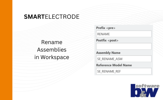
Rename Assemblies in Workspace
-
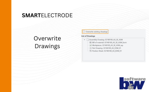
Overwrite Existing Drawings in SMARTElectrode
-
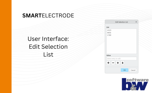
New User Interface to Edit Selection Lists in SMARTElectrode