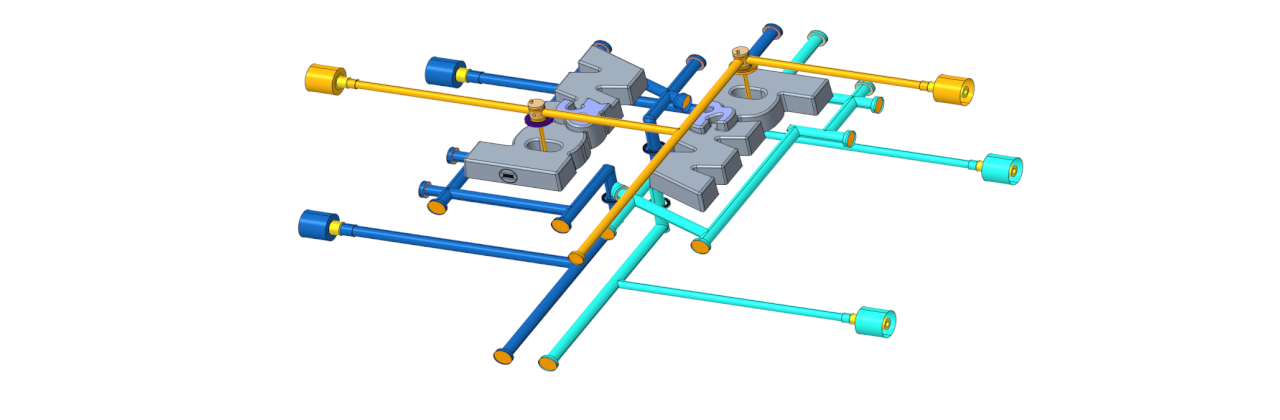
Enhancement of the Function for Generating the Fluid Circuit models in Expert Moldbase Extension
In this blog post, we present the enhancements to the “Create Fluid Circuit Models” function, which are available from releases
- 17.0.4.0 for Creo Parametric 11.0
- 16.0.8.1 for Creo Parametric 10.0
- 15.0.4.8 for Creo Parametric 9.0
- 14.0.4.8 for Creo Parametric 8.0
is available in Expert Moldbase Extension.

Mit dem Laden des Videos akzeptieren Sie die Datenschutzerklärung von YouTube.
Mehr erfahren
The feature to create a cooling circuit model is not new, but some customer requirements and requests have been improved.
- The algorithm for analyzing connected cooling holes has been improved. In addition to the EMX cooling bore holes and bore holes from Mold Design Waterline features, any other features can also be assigned to the cooling circuits. These features must be marked with the string parameter “BELONGS_TO_WATERLINE”.
- Note: “BELONGS_TO_WATERLINE” is an internal Creo parameter. If this parameter is assigned, then this feature is also taken into account in the wall thickness analysis in Mold Design, for example. How to use the wall thickness analysis can be read in this linked chapter of the EMX tutorial.
- A new radio group has been added to the dialog. Different assembly structures can be generated in the circuit model:
- Two subcomponents (ejector side/nozzle side) are generated. The surface copies of the cooling circuits are sorted into the subcomponents according to their side.
- Two subassemblies (ejector side/nozzle side) are created. In addition, a subcomponent is created for each connected circuit found and built into the assembly according to its side. Each circuit can be considered separately in an individual part.
- A subassembly is created for each original part that contains a cooling hole. This means that the cooling holes of each original part can be considered separately.
This could be interesting for you
-
Review: User Meeting – Toolmaking in Creo 2025
-
B&W Software at the Digitalization Conference 2025
-
Future of B&W has begun
-

No security alert of B&W License Server 11.19.1.0 regarding lmadmin
-

Potential issues in running B&W Software products in Creo 9.0 and 10.0
-

Meet us at the PTC/USER Global Summit 2024 in Orlando!
-
User Event Tooling 2023
-

Successful Windchill implementation project
-
New SMARTElectrode Versions released
-
New Releases for Expert Moldbase Extension 18.4.3.3, 17.0.8.0, 16.0.10.5, 15.0.5.3 available!
-
New function available in SMARTXHatch
-
New SMARTElectrode Versions released
-
Preliminary Program for Mold User Event 2025 Published
-
Enhancements and Bug Fixes for IFX Version 12.4.1.0 and 11.0.6.0
-
SMARTElectrode 18.4 for Creo Parametric 12.4 available
-
New SMARTElectrode Versions released
-
Invitation to Creo Mold User Event on November 11, 2025
-
New version for Expert Moldbase Extension 18.4.1.1, 17.0.6.0, 16.0.10.0, 15.0.5.0, 14.0.5.0 available!
-
Enhancements for IFX 10.0.9.0 and 11.0.5.0