Tip: How is it possible to edit plate dimensions which differ from the standard supplier sizes?
We received some customer requests regarding this specific change in the software. Hence, we want to get a bit more into detail to that in this blog post to provide a detailed source of information.
With the EMX releases 10.0 M032, 12.0.0.2 und 13.0.0.0 the software behavior was changed in a way that manual editing of plate dimensions in the plate dialog box is more restrictive.
In previous releases it was possible to simply edit all plate dimensions, without any restrictions. The advantage was that experienced designers were able to flexibly edit plates in any way they wanted. At the same time you needed to be aware that through these changes it was possible to create plate models whose dimensions no longer match to the supplier’s order number.
Due to that, we decided that the manual editing of plate dimension should not be available by default.
For this reason the following possibilities are not available anymore by default:
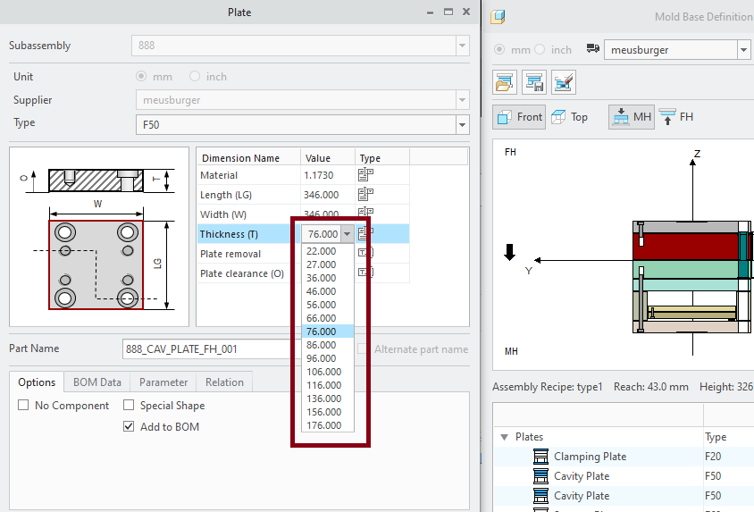
a) The main plate dimensions (e.g. plate thickness) can not be edited manually. In the pull-down menu the values provided by the supplier are listed only.
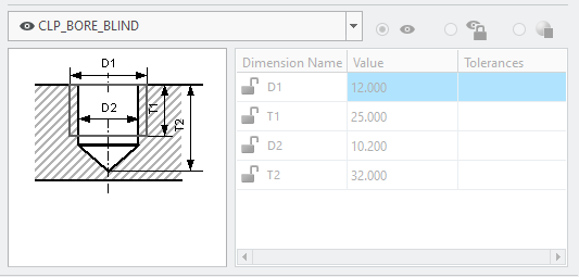
b) Feature status und dimensions can also not be edited anymore. The features (bore holes etc.) should fit to the supplier standard.
How is it now possible to apply manual changes to the plates anyway?
With the option Special Shape the restrictions can be suspended. In case this option is enabled a message dialog box appears which informs the user that manual editing is now possible and that one should be aware that differences between the supplier standard and the actual model can occur.
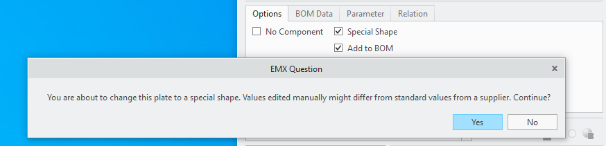
Plate features and dimensions can now be edited.
Additionally, further restrictions are still active regarding the plate length and width. In case special main dimensions are required, the user needs to switch to the “P” type. After doing so, the length and width can also be edited manually.
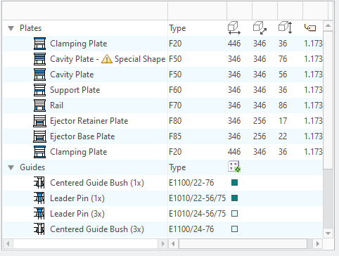
In case a plate is declared as “Special Shape” it is also visible in the summary tree of the mold base definition dialog box.
We are constantly working to improve our software. Please feel free to give us feedback.
This could be interesting for you
-

PTC/USER Agenda
-

Fachkonferenz Digitalisierung 2026 in Stuttgart
-
Join us at PTC/USER Global Summit 2026
-
Review: User Meeting – Toolmaking in Creo 2025
-

Future of B&W has begun
-

No security alert of B&W License Server 11.19.1.0 regarding lmadmin
-

Potential issues in running B&W Software products in Creo 9.0 and 10.0
-

Meet us at the PTC/USER Global Summit 2024 in Orlando!
-
User Event Tooling 2023
-

Successful Windchill implementation project
-
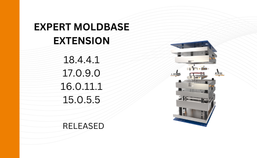
New versions of the Expert Moldbase Extension (18.4.4.1, 17.0.9.0, 16.0.11.1, 15.0.5.5) are now available!
-
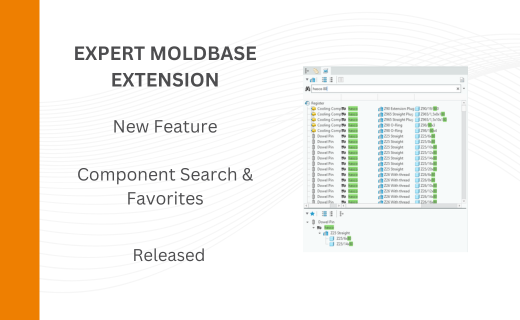
New Component Search in the Expert Moldbase Extension
-

MAIT Techworld Austria 2026 in Pasching
-
New SMARTElectrode Versions released
-
New Releases for Expert Moldbase Extension 18.4.3.3, 17.0.8.0, 16.0.10.5, 15.0.5.3 available!
-
New function available in SMARTXHatch
-
New SMARTElectrode Versions released
-
Preliminary Program for Mold User Event 2025 Published