Beamingly Beautiful and Simple SMARTOptics
- Optical path analysis based on geometric optics
- Complete integration with Creo Parametric
- Support of the design engineer already during the conception phase
- Determination of interference geometries
- Visualization of the results
- Support of different wavelengths
Benefits for your company
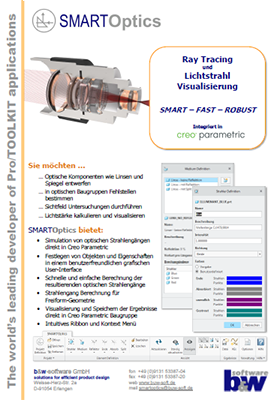
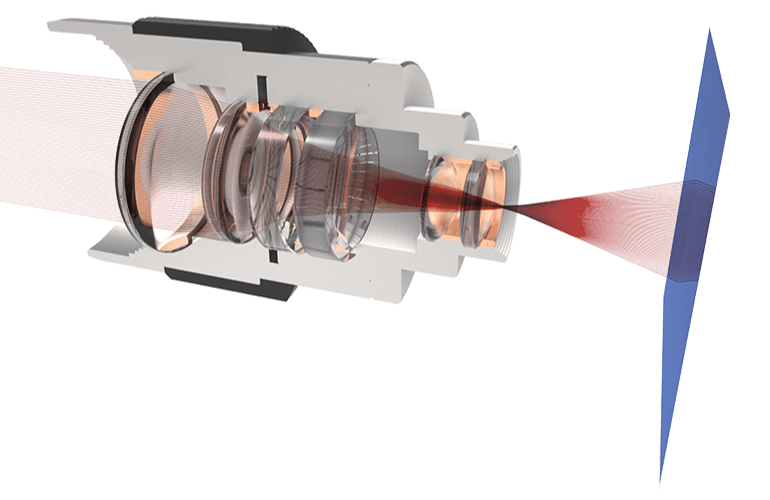
SMARTOptics provides a tool that you can use to simulate the optical path in Creo Parametric. The full integration enables immediate reaction to unforeseeable disturbance factors in the project phase. This saves time and money and shortens the product development process.
All types of geometric optics such as reflections and refraction are supported. The light is displayed in form of individual beams. The accuracy of the results is adequate and sufficient for most cases in technical optics.
-
Intuitive
The clear arrangement of the commands and an intuitive workflow will help you to complete the optical design quickly and simplifies the use of the software.
-
Flexible
You can react to changed boundary conditions at an early stage of the analysis. This increases the flexibility in your company and shortens the development time.
-
Integrated
In comparison to other optical software packages, the analysis is done directly in Creo Parametric and you can perform it yourself.
-
Manifold
You will have an access to an extensive material library and select material properties from various catalogs.
Video
Here you will find the current video that will bring SMARTOptics closer to you.
Functionalities
Define Optical Components

The following optical elements can be defined:
- Light sources / Spotlights – Light sources are Creo elements with any kind of curves. For each curve, a beam is sent through the assembly and analyzed.
- Material / Medium – On media the rays are refracted according to the refractive indices. Select the wavelength dependent material properties from a database.
- Reflective elements – parts where rays are reflected. You can specify the degree of reflection.
- End elements – parts where the beam to be evaluated should end.
- Absorbing elements – The beam is absorbed at these elements and ends here.
- Divider surfaces – Here the beam is divided into two beams. You can specify the degree of reflection.
Use Material Database
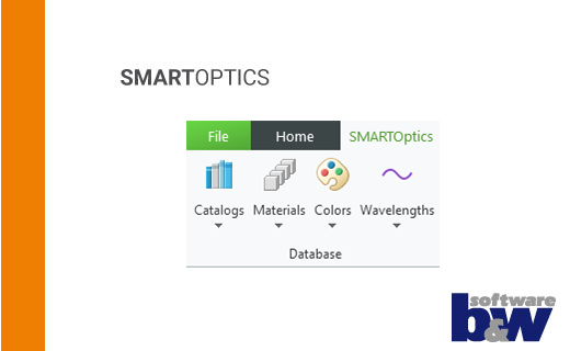
SMARTOptics offers an extensive glass database with materials from HOYA, OHARA and SCHOTT.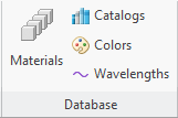
Of course, this database can be extended with your own materials at any time. In addition to the materials, it is also possible to define colors and wavelengths in order to refer to them later on.
Visualize Results
The result is temporarily displayed in the assembly.

It is also possible to generate the results as geometry in the form of curves or points in Creo Parametric. This also allows cooperation with partners who do not use SMARTOptics.
Support the use of different wavelengths
SMARTOptics supports the use of different wavelengths for your light sources. Check how your product behaves at different wavelengths and compare the results.
Possible Use Cases of SMARTOptics
-
Optical Assemblies
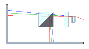
Any type of assemblies with mirrors or lenses.
-
Design Study
Use multi-function studies to determine variances of the target beam depending on tolerances.
-
Mechanism Simulation
How does the light behave on moving parts?
-
Fibre Optics
Does the light stay in the fibre optics?
-
Field of View Investigations
What are the effects of components in the field of view? Where, for example, do blind spots occur?
Technical details
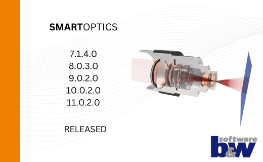
Find out about the supported Creo® versions
in our product calendar.
More information?
Request Demo Version
Have we aroused your interest?
Then you are welcome to request a demo version from us here.
